Monday, August 31, 2009

Configuration of Cisco Catalyst Express-500 Switch

In this document i will brielfy explain about the initial configuration / pocedure of Cisco Catalyst Express-500 series switches. The information in this document was created from the devices in a specific lab environment in my own office where i am working as i was asked to check this switch and try for all the configurations like VLAN, Ether-channel, Inter-Vlan Routing etc.

Now lets look at the steps to access the switch, Follow the steps in the same order as given to complete the configuration :)

1. Make sure to unplug all device from switch if connected

2. Power the switch

3. Wait for the SETUP LED to blink green

4. Press Setup, A switch port LED begins to blink green

5. When a switch port LED blinks green, connect your PC to that port (normally FastEthernet 0/1)

The LAN adapter of this PC (attached to the switch) must be configured to get the IP address via DHCP. The LEDs on the PC and the switchport blink green while the switch configures the connection (this takes around one minute)

6. Open a web browser, access your switch through IP and it should display the GUI, if not display then follow the followinf steps

a. Issue the ipconfig command in order to view the dynamic address allocation.


The switch configures its management address as the Default Gateway for the LAN adapter card of the PC.

Note: For Cisco IOS Software FY series releases, the management IP address is 10.0.0.1. For Cisco IOS Software SEG series releases, the IP address is 169.254.0.1: "Source is cisco.com for this note"

b. From the browser, go to the mentioned IP address. For example, http://10.0.0.1

7. Enter the Network Settings and Optional Settings (if required). Click Submit in order to save changes and finish the basic configuration.


8. Enter the configured User Name and Password in order to continue the configuration of the switch.


9. Then it will ask you for configuration of smart port, so just click on "no thanks"

10. In last it will display a prompt "Restart the switch with its current settings" and "Reset the switch to its factory default, and then restart the switch", so select the first option "Restart the switch with its current settings" and press "submit".

11. Close the web browser and reconfigure the LAN adapter with an IP address within the same subnet of the new management address of the switch.

12. When the switch restart, open a web browser and go to http://CE-500_Management_IP_Address, For example, http://172.16.100.100

I hope it will be informative for you :)

Sunday, August 23, 2009

DMVPN - EIGRP, Disable Split-Horizon

I was ask to tell the solution for the following question regarding DMVPN.

Q: I am deploying a DMVPN hub and spokes with mGRE tunnels protected by IPSEC. I activated EIGRP on it, and I noticed that on the spoke EIGRP
installs in its routing table only the route to the hub, while the spoke-to-spoke routes don't appear neither in the routing table, neither in the EIGRP topology. Nevertheless, the spokes communicate between them through the dynamic tunnels.
I couldn't find any Cisco document contemplating the issue. I wonder if this is the way it's supposed to work, or if I have to search for some misconfiguration.


Solution:

There are certain rules which we have to remember while configuring DMVPN with EIGRP, One of these rules is split horizon. The DMVPN hub tunnel interface serves multiple spokes. Also the tunnel ip address is on the same subnet as its spokes. When configuring a EIGRP AS you use the tunnel network id as a network you want to participate on with EIGRP.

Split Horizon was designed to not allow a router to advertise a route out the same interface in which the route was originally learned. This conflicts in the case of the tunnel interface because it needs to be able to make neighbors with the spokes on the same subnet and also re-advertise routes learned from one spoke to the next.

Again, If you dont disable split horizon on the tunnel interface you will only see the routes the hub itself is responsible for from a spoke router. This can be done by a single command under tunnel interface.
# no ip split-horizon eigrp 2

Now you can see all routes in the client routing table.

Cheers :)

Tuesday, August 18, 2009

GRE/IPSEC and IPSEC VPN tunnels

GRE is used as a it provides pure tunneling see GRE for full information. To make secure the GRE tunneling we use GRE/IPSec or IPSec VPN tunnel, as it is one way of setting up private site-to-site connection by utilizing public network (the Internet). Since it is utilizing public network, there would be no need to have dedicated physical circuit to interconnect the sites, hence requiring low overhead to setup while maintain private and secure connection.

With site-to-site IPSec VPN, there is a IP routing in place to interconnect multiple subnet. This IP routing could be static routing or dynamic routing. In a small network where there is only one path connecting two sites, then static routing should be sufficient. When there are multiple paths connecting two sites, then dynamic routing (i.e. EIGRP, OSPF) should be used to have optimal connection just like i did for our office as we have multiple sites to connect and communicate so we used dynamic routing (EIGRP) although we use DMVPN (i will talk about it in next blogs).

Note that IPSec tunneling technology is only able to support static routes and basic IP interconnection. When there are more advance IP interconnections needed, such as running Novell IPX, dynamic routing, and load balancing between the sites, then IPSec tunneling itself is unable to support. For such advance IP interconnections, GRE tunneling is the choice. The downside of GRE tunneling is that GRE tunnel is less-secure tunnel compared to IPSec tunnel.

As we use dynamic routing and decided to use public network and also want to have a secure connection, so the workaround is to run GRE over IPSec. IPSec will then be encrypting the GRE tunnel securely and GRE tunnel will be providing the advance IP interconnection support. The Header will look like this (Rough sketch form me sorry for so simple :(


For the detail configuration of GRE and VPN look at my blogs.

I hope this will be informative for you.

Cheers :)

GRE Tunnels

GRE stands for "Generic Routing Encapsulation". GRE is now industry tunneling method used to create a logical "TUNNEL" interface. It is designed to work with logical protocols, only GRE is completely non-secure as we have no concept of crypto-map. This makes a seperate network over the network, but now they add an IP header in the GRE header so makes it secure and provides a perfect tunneling. I will talk about GRE tunneling here, lets look at the configurations of GRE.


Run EIGRP on both sides

ReedWood(config) # router eigrp 1
ReedWood(config-router) # network 10.0.0.0
ReedWood(config-router) # network 41.0.0.0

PineWood(config) # router eigrp 1
PineWood(config-router) # network 10.0.0.0
PineWood(config-router) # network 41.0.0.0

Now to create tunnel on both side lets look at the configurations
ReedWood(config) # interface tunnel 0
# ip address 10.5.1.2 255.255.255.0
# tunnel source 0/0
# tunnel destination 41.95.110.2
# tunnel mode gre ip

PineWood(config) # interface tunnel 0
# ip address 10.5.1.1 255.255.255.0
# tunnel source 0/0
# tunnel destination 41.95.110.1
# tunnel mode gre ip

At this point for simplicty define static route on Router-A and check the connectivity
Router-A (config) # ip route 0.0.0.0 0.0.0.0

PineWood # show ip eigrp neighbor


It will shows you that the route is learned via Tunnel.

I Hope this will be informative for You !

Cheers :)

Wednesday, August 12, 2009

VPN Site-to-Site CLI Configuration

We are going to configure site-to-site VPN (site-to-site) between head office (Lahore) and our regional office (Peshawar), so here i am going to briefly discuss VPN i.e


1. How VPN are established
2. Configuring IKE Phase-1 parameters
3. Configuring IKE Phase-2 parameters
4. Configuring Interesting Traffic
5. CLI configuration

Cisco Router Perspective of VPN Connection

1. The routers recieve traffic considered "WORTHY" of establishing a VPN connection.
2. IKE Phase-1 negotiated, security association (SA) established.
3. IKE Phase-2 negotiated, security association established.
4. Data tranmitted through IPSec tunnel.
5. Once transmission complete, IPSec tunnel turn down (If you configure Time).

**: After 24-hours it can re-negotiated session key
**: After certain amount of data can re-negotiate the key.

Configuration:

1. Set up ISKAMP Policy (IKE Phase-1)
2. Set up IPSec Transform set (IKE Phase-2)
3. Define Interesting Traffic
4. Set up Crypto Map
5. Assign Crypto Map to Interface
PSH-Router(config) # crypto isakmp policy 50
PSH-Router(config-isakmp) # authentication pre-share
PSH-Router(config-isakmp) # encryption aes 128
PSH-Router(config-isakmp) # group 2
PSH-Router(config-isakmp) # hash sha
PSH-Router(config-isakmp) # lifetime 5000
PSH-Router(config-isakmp) #exit

PSH-Router(config) # crypto isakmp key 0 cisco address 71.209.254.34

PSH-Router(config) # crypto ipsec transform-set DEMO esp-aes 128 esp-sha-hmac
PSH-Router(cfg-crypto-trans) #

PSH-Router(config) # ip access-list extended INT_TRAFFIC
PSH-Router(config-ext-nacl) # permit ip 172.30.0.0 0.0.255.255 192.168.1.0 0.0.0.255
PSH-Router(config-ext-nacl) # exit

Note: This is not Permit or Deny ACL, this means encrypt this traffic.
PSH-Router(config) # crypto map VPN_MAP 10 ipsec-isakmp
PSH-Router(config-crypto-map) # set peer 71.209.254.34
PSH-Router(config-crypto-map) # match address INT_TRAFFIC
PSH-Router(config-crypto-map) # set transform-set DEMO

PSH-Router(config) # interface fastethernet 0/1
PSH-Router(config-if) # crypto map VPN_MAP


Head office configuration:

And same configuration is required on the other side with just a bit of changes, lets c

Head-Office(config) # crypto isakmp policy 50
Head-Office(config-isakmp) # authentication pre-share
Head-Office(config-isakmp) # encryption aes 128
Head-Office(config-isakmp) # group 2
Head-Office(config-isakmp) # hash sha
Head-Office(config-isakmp) # lifetime 5000
Head-Office(config-isakmp) #exit

Head-Office(config) # crypto isakmp key 0 cisco address 130.13.140.129

Head-Office(config) # crypto ipsec transform-set DEMO esp-aes 128 esp-sha-hmac
Head-Office(cfg-crypto-trans) #

Head-Office(config) # ip access-list extended INT_TRAFFIC
Head-Office(config-ext-nacl) # permit ip 192.168.1.0 0.0.0.255 172.30.0.0 0.0.255.255
Head-Office(config-ext-nacl) # exit

Head-Office(config) # crypto map VPN_MAP 10 ipsec-isakmp
Head-Office(config-crypto-map) # set peer 130.13.140.129
Head-Office(config-crypto-map) # match address INT_TRAFFIC
Head-Office(config-crypto-map) # set transform-set DEMO

Head-Office(config) # interface fastethernet 0/4
Head-Office(config-if) # crypto map VPN_MAP


I used group-2 in my configuration, actually we have different diffie helmin groups like group-1 is less processor intensive but encryptio is weak (768-bit), group-2 is processor intensive but provides high bit encryption (1024-bit) and group-5 provides even more (1536-bit) encryption. so it depends on you which ever group you are using.

I hope this will be informative for You :)

Any suggestion and comments will be highly appreciated.

Cheers :)

Tuesday, August 11, 2009

Understanding the IOS File Name Convention

As a network guy we should know about the naming convention of the IOS file name, which is usually similar to this form:

xxxx-yyy-ww.aaa-bb.bin

1. The xxxx is the platform, For example,

c1005 – For 1005 platform

c1600 – For 1600 platform

c1700 – For 1700, 1720, and 1750 platforms

c2500 – For 25xx, 3xxx, 5100, and AO (11.2 and later only) platforms

c2600 – For 2600 platform

c2800 – For Catalyst 2800 platform

c2900 – For 2910 and 2950 platforms

c3620 – For 3620 platform

c3640 – For 3640 platform

c4000 – For 4000 platform (11.2 and later only)

c4500 – For 4500 and 4700 platforms


2. The yyy is the feature set. For example,

b For Apple talk support

boot For boot image

c For CommServer lite (CiscoPro)

drag For IOS based diagnostic image

g For ISDN subset (SNMP, IP, Bridging, ISDN, PPP, IPX, and AppleTalk)

i For IP sebset (SNMP, IP, Bridging, WAN, Remote Node, and Terminal Services)

n For IPX support

q For asynchronous support

t For Telco return (12.0)

y For reduced IP (SNMP, IP RIP/IGRP/EIGRP, Bridging, ISDN, and PPP) (c1003 or c1004)

z For managed modems

40 For 40 bit encryption

50 For 50 bit encryption


3. The ww is for the format (where the IOS file runs in the router)

f For flash

m For RAM

r For ROM

l For the image will be relocated at run time

The file might also be compressed. The following letters denote the compression type,

z For zip compression

x For mzip compression

w For “STAC” compression


aaa-bb represent the version of the IOS. It is usually read like this “Version aa.a(bb)”. The last part of the IOS file name might contain letters like T (new feature release identifier), S (individual release number), or XR (modular packages).

Monday, August 10, 2009

Add a login banner to your Cisco router

I seen many people who just use banner for some welcome messages and stuff like that but we can use it in many usefull manners say like when i telnet or ssh so it should display me some warning message like "Unauthorized Access prohibited", say may be we want to display password if we changed that and let want the second shift administrator to know about it etc or we can also use it like to display the hostname, domain name etc so here is a small view of it, have a look :)

The syntax of banner is as follow:

PSH-DXX (config) # banner motd {char} {banner text} {char}

where {char} is a special delimeter character that does not exist in the {banner text}. Everything contained between the first and second {char} characters, including carriage returns, is interpreted as the banner message. For example,
PSH-DXX (config)# banner motd #

******************************************
* Unauthorized access prohibited
******************************************
#

OR we can have this in some more detail like as shoen
PSH-DXX (config)# banner motd #

-------------------------------------------
Unauhorized Access Prohibited
-------------------------------------------
You have access $(hostname).$(domain)
You are accessing line $(line)
-------------------------------------------
Unauhorized Access Prohibited
-------------------------------------------

The output of the banner is as:


I hope it will be informative for you :)

Sunday, August 9, 2009

openssl command-line program

The openssl command can be used to create digests of a file, which can be used to verify that a file has not been tampered with:

$ echo "test file"> foo.txt

$ openssl dgst -md5 foo.txt

MD5(foo.txt)= b05403212c66bdc8ccc597fedf6cd5fe
$ openssl dgst -sha1 foo.txt

SHA1(foo.txt)= 0181d93fee60b818e3f92e470ea97a2aff4ca56a

To view the other message digests that can be used, look at the output of openssl list-message-digest-commands.

You can also use openssl to encrypt files. To view the list of available ciphers, use openssl list-cipher-commands. Once you’ve chosen a cipher to use, you can encrypt the file using the following commands:
$ openssl enc -aes-256-cbc -salt -in foo.txt -out foo.enc

enter aes-256-cbc encryption password:
Verifying - enter aes-256-cbc encryption password:
$ file foo.enc

foo.enc: data
$ cat foo.enc

Salted__yvi{!e????i"Yt?;(Ñ° e%
$ openssl enc -d -aes-256-cbc -in foo.enc

enter aes-256-cbc decryption password:
test file

In the above example, the file foo.txt was encrypted using 256-bit AES in CBC mode, the encrypted copy being saved as the file foo.enc. Looking at the contents of the file provide gibberish. Decrypting the file is done using the -d option, however keep in mind that not only do you need to remember the password, you also need to know the cipher used.

I hope it will help You :)

Saturday, August 8, 2009

Periodical Configuration Save of Cisco Devices

Periodical configuration save of Cisco devices can be done from inside the device by using a combination of "kron" and "archive" commands. As we had no routine of taking backup of our router but yesterday after a long search now i have successfully configured all stuff like backup, monitoring my router through Nipper (see my full blog on it, click Nipper), Now i will take my backup and will save at remote place :).

Define the location of your configuration save apart from the default Flash location. Based on your IOS support, this can be a HTTP, HTTPS, FTP, or TFTP path. I am taking the backup using tftp.

The following commands is used to enable archive and define the path, while third command is used that when ever someone copy configuration to NVRAM so it will take backup also.

PSW-DXX (config) # archive
PSW-DXX (config-archive)# path tftp://10.110.1.22/
PSW-DXX(config-archive) # write-memory


If you want to suppress the display of password information in configuration log files, use the hidekeys command in configuration change logger configuration mode. or To allow the display of password information in configuration log files, use the no form of this command

PSW-DXX (config)# archive
PSW-DXX (config-archive)# log config
PSW-DXX (config-archive-log-cfg)# hidekeys or no hidekeys
PSW-DXX (config-archive-log-cfg)# exit


To enable the logging of configuration changes, use the logging enable command in configuration change logger configuration mode. To disable the logging of configuration changes, use the no form of this command.

PSW-DXX (config-archive-log-cfg)# logging enable
or
PSW-DXX (config-archive-log-cfg)# no logging enable


To specify the maximum number of entries retained in the configuration log, use the logging size command in configuration change logger configuration mode. By default value is 100. To reset the default value, use the no form of this command.

PSW-DXX (config-archive-log-cfg)# logging size 200


2. KRON

Define the policy list for the scheduler. The following is calling the "write config" command which will trigger the copy over network from the above:

PSW-DXX (config) # kron policy-list backup-config
PSW-DXX (config-kron-policy) # cli write memory


Define the schedule of the policy. The following example is for ten minutes past evening, everyday:

PSW-DXX (config) # kron occurrence daily-config-backup at 05:10 recurring
PSW-DXX (config-kron-occurrence) # policy-list backup-config


Note: Every time the "write memory" command is issued, the device will trigger a network copy to the path specified above.

I hope this will be informative for you. :)

Cheers :)

Friday, August 7, 2009

Audit your Cisco router's security with Nipper

While recently googling on a net, I learned about Nipper. Although there are many security tools that i studied which is used to perform security audits of network devices, but i found Nipper unique, so i configure this on our office (SNGPL) production router.

What is Nipper (Network Infrastructure Parser), Nipper is an open source network devices security auditing tool. One benefit of being open source is that it’s free :)Previously known as CiscoParse, Nipper isn’t especially polished, but it is very functional. It was easy to install and easy to use.

Even more impressive :) is that it works with many different types of network devices (and not just Cisco). Here’s a list of compatible network devices that Nipper can audit:

Cisco switches (IOS)
Cisco routers (IOS)
Cisco firewalls (PIX, ASA, FWSM)
Cisco Catalyst switches (NMP, CatOS, IOS)
Cisco Content Service Switches (CSS)
Juniper NetScreen Firewalls (ScreenOS)

How to use NIPPER ?

Nipper supports a lot of devices and provides many options, so I here i can’t possibly demonstrate all those options. what i do is to show you the basic demonstration. For our example, we’ll use Nipper to audit a Cisco router that has only the default configuration.

To begin, I took a Cisco 1841 router. First, download Nipper from SourceForge.net it’s available for both Windows and Linux. Extract it to a folder on your local PC; let’s call it C:\nipper as i have done like this.

Next, obtain a text version of the router’s configuration file. Telnet or SSH to the router, use the show running-configuration command, copy and paste the output into Notepad, and save it to your local PC in the aforementioned C:\nipper directory.

Alternatively, you can use a TFTP server and copy the configuration to your local PC. For example, I tried this using Tftpd32.exe, and it was both quick and easy. Use the following command to copy the file if some one don't know how to do :)

PSW-DXX # copy startup-config tftp:
Address or name of Remote Host: 10.110.1.22
Destination filename[startup-config] yes
!!!!!!!!!!!!!!!!!!!!!!!!!!!!!!!!!!!!!!!!!!!!!!!!!!!!!!!!! OK :)


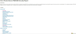
Once you have the running configuration that you want to audit on your PC, go to the Windows command prompt, and CD into the Nipper directory. Run the following, as shown in Figure A:


C:\nipper> nipper --ios-router --input=startup-config.txt --output=audit.html


The system will immediately return you to the command prompt without providing any information. But don’t worry — it worked.

Next, open a Web browser and enter this URL: c:\nipper\audit.html. This will take you to the security report. Figure B offers a screenshot of the audit.


What does Nipper tell you?

Scrolling through this report, you’ll see that Nipper provides security audit information such as:

1. A software version that has vulnerabilities and the reference numbers for those vulnerabilities
2. Recommendations to disable services that might cause others to be able to access the router
3. Commands that you need to enable to secure the router
For our example, Nipper told us that we need to do the following:

a): Upgrade the router’s IOS needs to prevent vulnerability to a Telnet remote DoS attack and a TCP listener DoS attack.
b): Configure the service tcp-keepalives-in command to help prevent a DoS attack.
c): Configure timeouts on consoles to prevent anyone from gaining access to the router from a Telnet or console session.
d): Configure the HTTP service as secure with HTTPS, and enable authentication.
Enable logging.

In addition to several other recommendations, Nipper provided a summary of the device’s configuration — what services are turned on or off, status of the lines, status of the interfaces, DNS, time zone, and more. Check out the actual report from our example.

Considering that it’s so small, simple, and free, Nipper is an amazingly powerful network device security auditing tool. For help with Nipper, run the C:\nipper\nipper -help command at the command prompt after you’ve downloaded, extracted, run the program.

I hope it will be informative for you as i found it very useful :)

Enjoy!

10 commands you should master when working with the Cisco IOS

The Cisco IOS provides thousands of commands, and configuring it can be challenging. Here are 10 commands that we should need to know while using the Cisco IOS.

1: " ? " (Help):

The "?", It may seem entirely too obvious that you should know how to type ? to ask for help when using the Cisco IOS. However, the Cisco IOS is completely different from other operating systems when it comes to using the question mark (help key). As the IOS is a command-line operating system with thousands of possible commands and parameters, using the ? can save our day.

We can use the command in many ways. First, use it when you don’t know what command to type. For example, type ? at the command line for a list of all possible commands. we can also use ? when we don’t know what a command’s next parameter should be. For example, you might type show ip ? If the router requires no other parameters for the command, the router will offer cr (carrige return) means it is the only available option. Finally, use ? to see all commands that start with a particular letter. For example, show c? will return a list of commands that start with the letter c.

2: show running-configuration

The show running-config command shows the router, switch, or firewall’s current configuration. The running-configuration is the config that is in the router’s memory. You change this config when you make changes to the router. Keep in mind that config is not saved until you do a copy running-configuration startup-configuration. The shortcut for this command is sh run.

3: Save Configuration

This command will save the configuration that is currently being modified (in RAM), also known as the running-configuration, to the nonvolatile RAM (NVRAM). If the power is lost, the NVRAM will preserve this configuration. In other words, if you edit the router’s configuration, don’t use this command and reboot the router–those changes will be lost (if you want to do so). This command can be abbreviated copy run start. The copy command can also be used to copy the running or startup configuration from the router to a TFTP server in case something happens to the router.

Router # copy running-configuration startup-configuration


4: show interface

The show interface command displays the status of the router’s interfaces. Among other things, this output provides the following:

Interface status (up/down)
Protocol status on the interface
Utilization
Bandwidth
Errors
Delay
MTU

This command is essential for troubleshooting a router or switch. It can also be used by specifying a certain interface, like sh int fa0/0.

Router # show interface


or for specific interface

Router # show interface fastethernet 0/0


5: show ip interface

Even more popular than show interface are show ip interface and show ip interface brief. The show ip interface command provides tons of useful information about the configuration and status of the IP protocol and its services, on all interfaces. The show ip interface brief command provides a quick status of the interfaces on the router, including their IP address, Layer 2 status, and Layer 3 status.

6: config terminal, enable, interface, and router

Cisco routers have different modes where only certain things can be shown or certain things can be changed. Being able to move between these modes is critical to successfully configuring the router.

For example, when logging in, you start off at the user mode (where the prompt looks like >). From there, you type enable to move to privileged mode (where the prompt looks like #). In privileged mode, you can show anything but not make changes. Next, type config terminal (or config t) to go to global configuration mode (where the prompt looks like router(config)# ). From here, you can change global parameters. To change a parameter on an interface (like the IP address), go to interface configuration mode with the interface command (where the prompt looks like router(config-if)#). Also from the global configuration mode, you can go into router configuration using the router {protocol} command. To exit from a mode, type exit.

Router >

Router >enable.............Router #

Router # configure terminal ......... Router (config) #

Router (config) # interface fasethernet 0/0

Router (config-if) #


7: no shutdown

The no shutdown command enables an interface (brings it up). This command must be used in interface configuration mode. It is useful for new interfaces and for troubleshooting. When you’re having trouble with an interface, you may want to try a shut and no shut. Of course, to bring the interface down, reverse the command and just say shutdown. This command can be abbreviated no shut.

8: show ip route

The show ip route command is used to show the router’s routing table. This is the list of all networks that the router can reach, their metric (the router’s preference for them), and how to get there. This command can be abbreviated sh ip route and can have parameters after it, like shiproospf for all OSPF routers. To clear the routing table of all routes, you do clear ip route *. To clear it of just one route, do clear ip route 1.1.1.1 for clearing out that particular network.

Router # show ip route


9: show version

The show version command gives you the router’s configuration register (essentially, the router’s firmware settings for booting up), the last time the router was booted, the version of the IOS, the name of the IOS file, the model of the router, and the router’s amount of RAM and Flash. This command can be abbreviated shver.

10: debug

The debug command has many options and does not work by itself. It provides detailed debugging output on a certain application, protocol, or service. For example, debug ip route will tell you every time a router is added to or removed from the router.

Router # debug interface serial 0/1/0


I hope it will be informative for you :)

Thursday, August 6, 2009

Cisco HDLC (Why called Cisco HDLC ?)

High-level Data Link Control, a layer-2 (data-link layer) transmission protocol. The HDLC protocol embeds information in a data frame that allows devices to control data flow and correct errors. For any HDLC communications session, one station is designated primary and the other secondary. A session can use one of the following connection modes, which determine how the primary and secondary stations interact.

Normal unbalanced: The secondary station responds only to the primary station.

Asynchronous: The secondary station can initiate a message.

Asynchronous balanced: Both stations send and receive over its part of a duplex line. This mode is used for X.25 packet-switching networks.

The Link Access Procedure-Balanced (LAP-B) and Link Access Procedure D-channel (LAP-D) protocols are subsets of HDLC.

Q: Now question comes why it is called cisco HDLC? because cisco added some very important features like:

1. Keepalive Mechanism

2. Added serial link address resolution protocol (SLARP), It is used for the purpose of auto-installation like when router boot up so to fine the TFTP server, get the configuration including IP address etc.

I hope it will be informative for you!

3. Added STAC compression, Its a good one but very processor heavy.

4.
Performance Increase (7 - 12 Byte), The header size is increase and this is the beauty of HDLC and works efficiently across WAN.

I Hope this will be informative for You!

Error: %SNMP-3-DVR_DUP_REGN_ERR: Attempt for dupe

ERROR:

SEC 8:000049: Jan 31 22:25:00.760:
%SNMP-3-DVR_DUP_REGN_ERR: Attempt for dupe
regn with SNMP by driver having ifIndex 709 and ifDescr Tunnel0
-Traceback= 204128 204230 92DB90 92DF6C B2CF8C BBF368 BC00C8 1C4EFC 1C5524

1C60B8 1C655C 2EC5CC


Cisco IOS Release 12.4(13b) is a rebuild release for Cisco IOS Release 12.4(13). The caveats (warning) in this section are resolved in Cisco IOS Release 12.4(13b) but may be open in previous Cisco IOS releases.

The following information is provided for each caveat (warning):

•Symptoms—A description of what is observed when the caveat occurs.

•Conditions—The conditions under which the caveat has been known to occur.

•Workaround—Solutions, if available, to counteract the caveat.

Basic System Services
•CSCeb20967

Symptoms: A Route Switch Processor (RSP) may reload unexpectedly when a bus error with an invalid memory address occurs while packets are placed into a hold queue.

[1] "Conditions: This symptom is observed on a Cisco 7500 series that runs Cisco IOS Release 12.0 S, 12.1(14)E4, or 12.2 S when the following sequence of events occurs:

1. A packet is switched via Cisco Express Forwarding (CEF).

2. The egress interface has queueing/shaping configured.

3. The egress interface is congested, causing the packet to be placed into the hold queue."

Symptoms: The following SNMP error message and tracebacks are seen:

SEC 8:000049: Jan 31 22:25:00.760:
%SNMP-3-DVR_DUP_REGN_ERR: Attempt for dupe
regn with SNMP by driver having ifIndex 709 and ifDescr Tunnel0
-Traceback= 204128 204230 92DB90 92DF6C B2CF8C BBF368 BC00C8 1C4EFC 1C5524

1C60B8 1C655C 2EC5CC

Conditions: This symptom was see when new interfaces were added (or existing interfaces like tunnel come up) after bootup, or when new or existing interfaces come up after RPR+ switchover when running Cisco IOS Release 12.0(32)S6. Also, this symptom occurs if the snmp ifindex persist command is configured on the router.


Further Problem Description: Though customer traffic is not affected, this symptom does impact the SNMP stats and other SNMP data for both the original and the new interface. Usually the message is from the standby RP, so once that standby RP becomes active, the data from SNMP polls of these interfaces would not be accurate.

[1] www.cisco.com/en/US/docs/ios/12_4/release/notes

Monday, August 3, 2009

Virtual Links


Yesterday I was thinking of writing something related to OSPF so something crossed my mind and on that very moment I start to write about it, so here we go that is “VIRTUAL LINKS”.
Suppose we have a complicated network and we use OSPF as our IGP and we configure different areas in it, I assume that the reader of virtual link must know how to configure multiple area OSPF and what is the concept behind it, I will talk directly about the virtual link, what is it, how it works, and what is the purpose of virtual links.

When an area is not directly connected to area 0 (backbone area) so it can’t communicate, a concept is used for it and that is called Virtual Links make able the area to communicate. See figure a, we have two routers namely R1 and R2, The fastethernet of R1 is configured under area 0, link between R2 and R1 is configured under area 1 and R2 fastethernet is configured under area2, now the LAN of R2 will not be able to communicated to R1 as it is not directly connected to R1 so we have to configure Virtual Link between R1 and R2 so what it will do is that the area 0 will be expand logically to R2 covering area 1 with it, now from R2 point of view there will two areas area 0 and area 2.

1: In the figure, Area 2 is not directly connected to Area 0 so we have to create a transit link on Area 1 to make able the communication between Area 2 and Area 0.
2: Here the Area 0 expand logically
3: After Virtual the R2 becomes Area Boarder Router (ABR).

NOTE: If a router connects two areas but none of the area is Area 0 so the router will never be ABR.

Conditions for Virtual Links

1: Link between two routers when made so one of the router must be part of back-bone area (Area 0).
R1-------R2-------> Link can be configured
If we another router R3 connected to router R2
R2------R3------> Can’t configure link as non of the router is directly connected to area 0.
2: When link is made between two routers, so one area must be common between them like
R1-----R2 (Area 1 is common)
R1-----R3 (Nothing is common)

NOTE: For Virtual Link both he condition must be satisfied.

OSPF Configuration

A(config) # router ospf 1
A(config) # network 2.0.0.0 0.255.255.255 area 2
A(config) # network 200.100.100.0 0.0.0.255 area 2

B(config) # router ospf 1
B(config) # network 2.0.0.0 0.255.255.255 area 2
B(config) # network 3.0.0.0 0.255.255.255 area 1
B(config) # network 200.100.150.0 0.0.0.255 area 1

C(config) # router ospf 1
C(config) # network 3.0.0.0 0.255.255.255 area 1
C(config) # network 200.100.200.0 0.0.0.255 area 0


Virtual Link Configuration

B(config) # router ospf 1
B(config) # area 1 virtual-link 200.100.200.100

C(config) # router ospf 1
C(config) # area 1 virtual-link 200.100.150.100


Now check your Router-A routing table , the Router-C route will be there by using following command.

A # show ip route

Saturday, August 1, 2009

GUI Root Login Problem in Fedora-11

For the first time when i download Fedora-11 from the internet that was for "Live User" so after installation i try to login as a root from GUI so i was unable as it show "Unable to Authenticate User" so i thought may be it is not allowed for live user, but yesterday i installed the full version of Fedora-11 but still i was unable to login as root through GUI although i can from terminal so after some goggling i found that Fedora-11 by default doesn't allow someone to login as root through GUI. Instead you have to login as a normal user and become root through your terminal. However many users still want to login as root like me. Don't forget that once you login as root its easier to damage your system so don't do the following unless you are sure what you are doing.
Before doing any change just take backup of the file

$ cp /etc/pam.d/gdm /root

Step # 1

$ su -c 'gedit /etc/pam.d/gdm'

or

$ su

$ vi /etc/pam.d/gdm


Here in this file find the following line,

auth required pam_succeed_if.so user != root quiet

either delete or comment it better comment it

#auth required pam_succeed_if.so user != root quiet

Save the file and logout.

Step # 2

Do the same for /etc/pam.d/gdm-password

$ su -c 'gedit /etc/pam.d/gdm-password'

or

$ su

$ vi /etc/pam.d/gdm-password


Here in this file find the following line,

auth required pam_succeed_if.so user != root quiet

either delete or comment it better comment it

#auth required pam_succeed_if.so user != root quiet

Save the file and logout.

After this i was able to login successfully as a root through GUI.